Search This Blog

Powered by Blogger.

Translate

Augmented Reality (AR) Technology


Augmented Reality
Augmented Reality
Introduction

Since the early 70′s video games have been a great entertainment for all of us. With the recent boom in technology, computer graphics has been so advanced that graphic games are being introduced into the real world surroundings. The photo reality is mind boggling to such an extent that you feel that the games have been plucked out of your display monitors and integrated into your surroundings. Not only the video part, but also sound and also other sense enhancements are integrated into the real world. Such a technology is called Augmented Reality, which clearly makes us doubt whether what we see, hear, smell and feel is real or not.

What is Augmented Reality (AR)?

Augmented Reality [AR] can actually be defined as the integration of graphics into the physical real world without a single change in the perspective, that is every image shown will be adjusted to every angle of movement of the user’s head and eyes. Thus a widely produced graphics in augmented reality will surely enhance everyone’s perception of the real world.
Thus AR is a combination of three factors. They are
  • Real and virtual world.
  • Interaction in the real time.
  • 3D world.
With the wide use of AR, the entire view of the world will surely change. Just think of yourself, sitting at home, while an exact replica of yourself walking through the streets. When you view such a person’s image the audio will coincide with the image automatically. The changes will be made continuously to reflect the movements of your view. Such applications are most commonly seen nowadays in smart phones.

Technology

To know the technology used in AR it is necessary to know the basic components used in Augmented Reality. There are four basic components used in AR. They are
1. Display
2. Tracking and Orientation
3. Portable Computer
4. Software
These four components are combined together to make a highly efficient AR device. Devices like high speed multi-processors, high resolution cameras, accelerometers and are also used to enhance the reliability of the AR equipped device.
Now let us learn about each component in detail.

1. Displays

Tree types of displays are used in AR technology. They are
  • Head Mounted Displays [HMD]

This device keeps both the images of the real physical world and the virtual graphical world over the user’s world view. HMD are either an optically transparent or video transparent device. In an optically transparent display device, partial silver mirrors are used to pass the views of the real world through a lens. At the same time the virtual images are reflected into the user’s eyes. A 6-degrees of freedom [dof] sensor must be used to track the HMD device. Such a tracking method helps in relating the virtual world to the real world.
Some basic products that use such displays are Sony Glasstron, Microvision NOMAD and so on.
  • Handheld Displays

Such displays are small in size and will easily fit in one hand. These devices use video transparent techniques to relate the virtual world to the real world. Here also 6-degrees of freedom [dof] sensors are used apart from devices like GPS trackers, and digital compasses.  This display technology is the biggest success for Augmented Reality till now. Since they are easily portable and due to the bulk use of camera phones, they are used widely.
  • Spatial Displays / Spatial Augmented Reality [SAR]

This is very different from the other two techniques explained above. There is no need t carry the display, instead, the graphical image is related to physical objects by using a digital projector. The only problem is that the user will have no contacts with the display.
The main advantage of such a device when compared to other displays is that the user doesn’t have to carry the equipment along with him. Thus the users can easily see each other’s faces. Since a projector system is used, these displays have better resolution than the others. The resolution can be further increased by expanding the display area by using more projectors.

2. Tracking and Orientation

As the name refers, tracking and orientation is needed to know the user’s exact location in comparison to his surroundings and also is used for tracking the exact eye and head movements of the user. This is the most complex part of the Augmented Reality technology as three major functions such as tracking the overall location, movement of the user’s head and eye and adjusting the graphics to be displayed are done with utmost precaution. There has not been a single system than can produce AR without a small delay between the real world and the graphical world till now.

3. Portable Computer

For this technology to sustain, the computers used must have high speed processors. Even now, the computers used for this purpose, does not have enough efficiency. For using 3-D graphics in systems, the configuration must be high end.

Applications

Here are some of the applications of AR in different fields.
  • Gaming and Entertainment

This is the biggest field in which AR has really made progress in. The games can be enhanced to such an extent that the user will fell like he is one of the characters of the game. Even movies can be watched with such enthusiasm as you will feel that the characters are walking past you.
  • Education

AR system can be greatly helpful to students as it can be used to re-create historic events of great importance in relation to its real time background. Thus the students will have a better idea of all the facts in life, providing them with a better education.
  • Security and Defence

AR technology helps in giving the soldiers in the field vital information about their surroundings, friendly troops and also the movement of their enemies. Even police officers will have a great help from such a technology as they have a complete and inmost view of a crime scene or robbery.
  • Medicine

During a medical operation, AR technology can be used to provide the doctor a better sensory perception of the patient’s body.
Thus, the risk factor involved in an operation can be greatly reduced and the efficiency can be increased. The technology can also be used to provide the patient’s medical records digitally in page wise manner, immediately after an X-ray or MRI, so that a quick decision can be taken

Paint That Can Hide Airoplane


Carbon Nanotube Coating
Radar detection has always been the nightmare of military aircrafts. Once spotted in the radar zone, it is easy to destroy the aircraft in mid air by using anti-aircraft missiles. Defense personnel’s across the world are investing billions to develop better stealth equipped aircrafts that will easily escape from radar eyes.  The concept of stealth is applied on an aircraft by making changes in the aircraft design such that it deflects the radar beams instead of reflecting them. The aircraft design is such that there are no perpendicular sections in the body of the plane, so the radar beam never reflects back to the receiver.  While making a stealth aircraft we have to compromise with one of its main factor – the engine power. Though reducing the engine power can reduce the heat signature, the speed of the aircraft will also be compromised.  What if we could develop a better stealth technology without compromising the aircrafts’ speed?  We are talking about a technology that will make any aircraft invisible for radars.
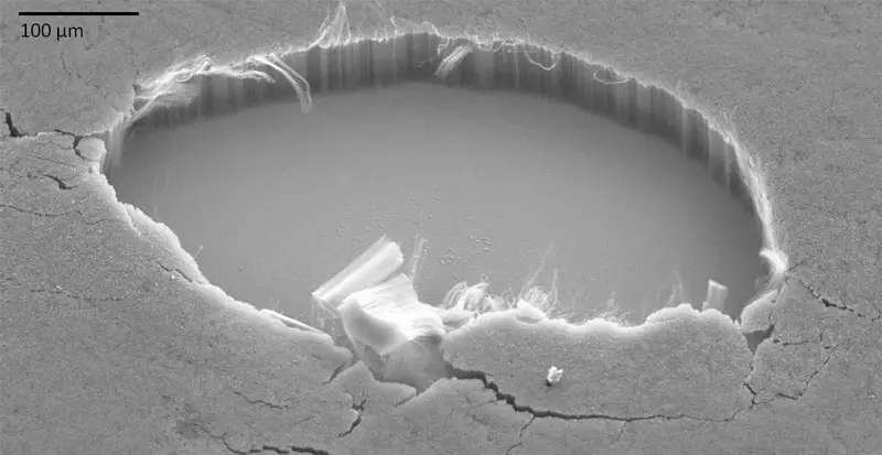
Researchers have invented a special nano tube paint to make any object ultra black. This concept is also used for making aircrafts invisible to radars.
Engineers of NASA developed carbon nano tubes, being the ‘blackest ‘known material for their space missions. Carbon nano tubes will absorb 99 percent of any light- ultraviolet, visible or infrared that strikes on it. The material is also known for its excellent electrical conductivity and high strength .Carbon nano tubes are tiny yet long tubular structures made of pure carbon.  A professor from Michigan University L J Guo first realized that by applying the nano paint or the nano tube coating, the aircraft could absorb the radar waves there by making it virtually invisible.
The researchers implanted large volumes of nano tubes into various substances like silicon wafer. Nano tubes have to be planted in a particular manner to make its reflective index similar to surrounding air. After implantation, the light is absorbed without being scattered. A practical method to implant nano tubes on the surface of aircrafts has not been developed until now. Perfect results were obtained only when nano tubes were implanted in tiny particles under the influence of high temperature and pressure. Guo suggested that first, the nano tubes has to be implanted in tiny particles and then suspended in the paint for stealth aircrafts. Earlier, to prevent absorption and radioactive properties, a metallic mixture was added to black paint and then coated on the aircraft. However, this would add excess weight to the machine. Since nano tube has ultra black property  and is denser, there is no need of any additives.

The difference Between Microprocessor and Micro-controller


When you start learning about Microprocessors (in most case you will begin with Intel 8085) andMicrocontrollers (usually you will begin with Intel 8051 from the MCS 51 micro controller family), the first question that pops up is “hey… what’s the difference in between” ? In this article I am explaining the basic differences and similarities between a microprocessor and micro controller. In fact you can call this article a simple comparison of both micro computing devices. This comparison will be same (at the basic level) for any micro processor and controller.  So lets begin.
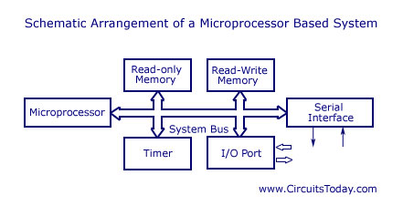
At the basic level, a microprocessor and micro controller exist for performing some operations – they are – fetching instructions from the memory and executing these instruction (arithmetic or logic operations) and the result of these executions are used to serve to output devices. Are you clear? Both devices are capable of continuously fetching instructions from memory and keep on executing these instructions as long as the power is not turned off. Instructions are  electronic instructions represented by a group of bits. These instructions are always fetched from their storage area, which is named as memory.  Now lets take a closer look at block diagrams of a microprocessor based system and a micro controller based system.

Microprocessor based system

microprocessor system - schematic arrangement
Take a closer look at the block diagram and you will see a micro processor has many support devices like Read only memory, Read-Write memory, Serial interface, Timer, Input/Output ports etc. All these support devices are interfaced to microprocessor via a system bus. So one point is clear now, all support devices in a microprocessor based system are external.  The system bus is composed of an address bus, data bus and control bus.
Okay, now lets take a look at the microcontroller.

Micro controller system

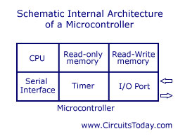
microcontroller schematic arrangement
The above block diagram shows a micro controller system in general. What’s the primary difference you see? All the support devices like Read only memory, Read – Write memory, Timer, Serial interface, I/O ports are internal. There is no need of interfacing these support devices and this saves a lot of time for the individual who creates the system. You got the basic understanding ? A micro controller is nothing but a microprocessor system with all support devices integrated inside a single chip. There is no need of any external interfacing in a micro controller unless you desire to create something beyond the limit, like interfacing an external memory or DAC/ADC unit etc. To make this microcontroller function, you need to give a DC power supply, a reset circuit and a quartz crystal (system clock) from external source.
Okay, so we have an idea about the basic difference between a microprocessor and microcontroller. Now lets compare some features of both systems.

Comparison

As you already know, support devices are external in a microprocessor based system where as support devices are internal for a micro controller. Micro controllers offer software protection where as micro processor base system fails to offer a protection system. This is made possible in microcontrollers by locking the on-chip program memory which makes it impossible to read using an external circuit. Okay! So that are basic differences, now you can come up with some more. As we need to interface support devices externally in a microprocessor based system, time required to build the circuit will be more, the size will be more and power consumption will be more in a microprocessor based system compared to microcontroller

Transistor amplifier


Transistor amplifier.

Amplifier is a circuit that is used for amplifying a signal. The input signal to an amplifier will be a current or voltage and the output will be an amplified version of the input signal. An amplifier circuit which is purely based on a transistor or transistors is called a transistor amplifier. Transistors amplifiers are commonly used in applications like RF (radio frequency), audio, OFC (optic fibre communication) etc. Anyway the most common application we see in our day to day life is the usage of transistor as an audio amplifier. As you know there are three transistor configurations that are used commonly i.e. common base (CB), common collector (CC) and common emitter (CE). In common base configuration has a gain less than unity and common collector configuration (emitter follower) has a gain almost equal to unity). Common emitter follower has a gain that is positive and greater than unity. So, common emitter configuration is most commonly used in audio amplifier applications.
A good transistor amplifier must have the following parameters; high input impedance, high band width, high gain, high slew rate, high linearity, high efficiency, high stability etc. The above given parameters are explained in the next section.
Input impedance: Input impedance is the impedance seen by the input voltage source when it is connected to the input of the transistor amplifier. In order to prevent the transistor amplifier circuit from loading the input voltage source, the transistor amplifier circuit must have high input impedance.

Bandwidth.
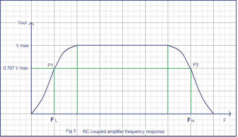
The range of frequency that an amplifier can amplify properly is called the bandwidth of that particular amplifier. Usually the bandwidth is measured based on the half power points i.e. the points where the output power becomes half the peak output power in the frequency Vs output graph. In simple words, bandwidth is the difference between the lower and upper half power points. The band width of a good audio amplifier must be from 20 Hz to 20 KHz because that is the frequency range that is audible to the human ear. The frequency response of a single stage RC coupled transistor is shown in the figure below (Fig 3). Points tagged P1 and P2 are the lower and upper half power points respectively.
frequency response transistor amplifier
RC coupled amplifier frequency response
Gain.
Gain of an amplifier is the ratio of output power to the input power. It represents how much an amplifier can amplify a given signal. Gain can be simply expressed in numbers or in decibel (dB). Gain in number is expressed by the equation G = Pout / Pin. In decibel the gain is expressed by the equation Gain in dB = 10 log (Pout / Pin). Here Pout is the power output and Pin is the power input. Gain can be also expressed in terms of output voltage / input voltage or output current / input current. Voltage gain in decibel can be expressed using the equation, Av in dB = 20 log ( Vout / Vin) and current gain in dB can be expressed using the equation Ai = 20 log (Iout / Iin).
Derivation of gain.
G = 10 log ( Pout / Pin)………(1)
Let Pout = Vout / Rout and Pin = Vin / Rin. Where Vout is the output voltage Vin is the input voltage, Pout is the output power, Pin is the input power, Rin is the input voltage and Rout is the output resistance. Substituting this in equation 1 we have
G = 10log ( Vout²/Rout) / (Vin²/Rin)………….(2)

Let Rout = Rin, then the equation 2 becomes
G = 10log ( Vout² / Vin² )
i.e.
G = 20 log ( Vout / Vin )

Efficiency.
Efficiency of an amplifier represents how efficiently the amplifier utilizes the power supply. In simple words it is a measure of how much power from the power supply is usefully converted to the output. Efficiency is usually expressed in percentage and the equation is  Î¶ = (Pout/ Ps) x 100. Where Î¶ is the efficiency, Pout is the power output and Ps is the power drawn from the power supply.
Class A transistor amplifiers have up to 25% efficiency, Class AB has up to 55% can class C has up to 90% efficiency. Class  A  provides excellent signal reproduction but the efficiency is very low  while Class C has high efficiency but the signal reproduction is bad. Class AB stands in between them and so it is used commonly in audio amplifier applications.
Stability.
Stability is the capacity of  an amplifier to resist oscillations. These oscillations may be high amplitude ones masking the useful signal or very low amplitude, high frequency oscillations in the spectrum. Usually stability problems occur during high frequency operations, close to 20KHz in case of audio amplifiers. Adding a Zobel network at the output, providing negative feedback etc improves the stability.
Slew rate.
Slew rate of an amplifier  is the maximum rate of change of output per unit time. It represents how quickly the output of an amplifier can change in response to the input. In simple words, it represents the speed of an amplifier. Slew rate is usually represented in V/μS and the equation is  SR = dVo/dt.
Linearity.
An amplifier is said to be linear if there is a linear relationship between the input power and the output power. It represents the flatness of the gain. 100% linearity is not possible practically as the amplifiers using active devices like BJTs , JFETs or MOSFETs  tend to lose gain at high frequencies due to internal parasitic capacitance. In addition to this the input DC decoupling capacitors (seen in almost all practical audio amplifier circuits) sets a lower cutoff frequency.
Noise.
Noise refers to unwanted and random disturbances in a signal. In simple words, it can be said to be unwanted fluctuation or frequencies present in a signal. It may be due to design flaws, component failures, external interference, due to the interaction of two or more signals present in a system, or by virtue of certain components used in the circuit.
Output voltage swing.
Output voltage swing is the maximum range up to which the output of an amplifier could swing. It is measured between the positive peak and negative peak and in  single supply amplifiers it is measured from positive peak to the ground. It usually depends on the factors like supply voltage, biasing, and component rating.

Common emitter RC coupled amplifier.

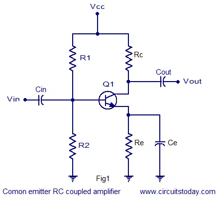
The common emitter RC coupled amplifier is one of the simplest and elementary transistor amplifier that can be made. Don’t expect much boom from this little circuit, the main purpose of this circuit is pre-amplification i.e to make weak signals strong enough for further processing or amplification. If designed properly, this amplifier can provide excellent signal characteristics. The circuit diagram of a single stage common emitter RC coupled amplifier using transistor is shown in Fig1.
transistor amplifier
RC coupled amplifier
Capacitor Cin is the input DC decoupling capacitor which blocks any DC component if present in the input signal from reaching the Q1 base. If any external DC voltage reaches the base of Q1, it will alter the biasing conditions and affects the performance of the amplifier.
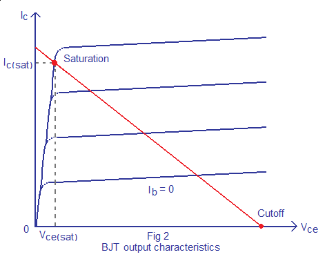
R1 and R2 are the biasing resistors. This network provides the transistor Q1′s base with the necessary bias voltage to drive it into the active region. The region of operation where the transistor is completely switched of is called cut-off region and the region of operation where the transistor is completely switched ON (like a closed switch) is called saturation region. The region in between cut-off and saturation is called active region. Refer Fig 2 for better understanding. For a transistor amplifier to function properly, it should operate in the active region. Let us consider this simple situation where there is no biasing for the transistor. As we all know, a silicon transistor requires 0.7 volts for switch ON and surely this 0.7 V will be taken from the input audio signal by the transistor. So all parts of there input wave form with amplitude ≤ 0.7V will be absent in the output waveform. In the other hand if the transistor is given with a heavy bias at the base ,it will enter into saturation (fully ON) and behaves like a closed switch so that any further change in the base current due to the input audio signal will not cause any change in the output. The voltage across collector and emitter will be 0.2V at this condition (Vce sat = 0.2V). That is why proper biasing is required for the proper operation of a transistor amplifier.
transistor output characteristics
BJT output characteristics
Cout is the output DC decoupling capacitor. It prevents any DC voltage from entering into the succeeding stage from the present stage. If this capacitor is not used the output of the amplifier (Vout) will be clamped by the DC level present at the transistors collector.
Rc is the collector resistor and Re is the emitter resistor. Values of Rc and Re are so selected that 50% of Vcc gets dropped across the collector & emitter of the transistor.This is done to ensure that the operating point is positioned at the center of the load line. 40%  of Vcc is dropped across Rc and 10% of Vcc is dropped across Re. A higher voltage drop across Re will reduce the output voltage swing and so  it is a common practice to keep the voltage drop across Re = 10%Vcc . Ce is the emitter by-pass capacitor. At zero signal condition (i.e, no input) only the quiescent current (set by the biasing resistors R1 and R2 flows through the Re). This current is a direct current of magnitude few milli amperes and Ce does nothing. When input signal is applied, the transistor amplifies it and as a result a corresponding alternating current flows through the Re. The job of  Ce is to bypass this alternating component of  the emitter current. If Ce is not there , the entire emitter current will flow through Re and that causes a large voltage drop across it. This voltage drop gets added to the Vbe of the transistor and the bias settings will be altered. It reality, it is just like giving a heavy negative  feedback and so it drastically reduces the gain.

Design of RC coupled amplifier.

The design of a single stage RC coupled amplifier is shown below.
The nominal vale of collector current Ic and hfe can be obtained from the datasheet of the transistor.
Design of Re and Ce.
Let voltage across Re; VRe = 10%Vcc ………….(1)
Voltage across Rc; VRc = 40% Vcc. ……………..(2)
The remaining 50% will drop across the collector-emitter .
From (1) and (2)  Rc =0.4 (Vcc/Ic)  and Re = 01(Vcc/Ic).
Design of R1 and R2.
Base current Ib = Ic/hfe.
Let Ic ≈ Ie .
Let current through R1; IR1  = 10Ib.
Also voltage across R2 ; VR2 must be equal to Vbe + VRe. From this VR2 can be found.
There fore VR1 = Vcc-VR2. Since VR1 ,VR2 and IR1 are found we can find R1 and R2 using the following equations.
R1 = VR1/IR1 and R2 = VR2/IR1. 
Finding Ce.
Impedance of emitter by-pass capacitor should be one by tenth of Re.
i.e, XCe = 1/10 (Re) .
Also XCe = 1/2∏FCe.
F can be selected to be 100Hz.
From this Ce can be found.
Finding Cin.
Impedance of the input capacitor(Cin) should be one by tenth of the transistors input impedance (Rin).
i.e, XCin = 1/10 (Rin)
Rin = R1 parallel R2 parallel (1 + (hfe re))
re = 25mV/Ie.
Xcin = 1/2∏FCin.
From this Cin can be found.
Finding Cout.
Impedance of the output capacitor (Cout) must be one by tenth of the circuit’s output resistance (Rout).
i.e, XCout = 1/10 (Rout).
Rout = Rc.
XCout = 1/ 2∏FCout.
From this Cout can be found.
Setting the gain.
Introducing a suitable load resistor RL across the transistor’s collector and ground will set the gain. This is not shown in  Fig1.
Expression for the voltage gain (Av) of a common emitter transistor amplifier is as follows.
Av = -(rc/re)
re = 25mV/Ie
and rc = Rc parallel RL
From this RL can be found

Page Rank

google pagerank

Write For Us

Submit a Guest Post

Find us on Facebook

Categories

555 Timer IC 7 segment Display 8051 Project AC Circuits Adafruit Alarms Amplifier Circuits Analog Circuits android Arduino arm processor Assembly Languange Atmel Atom Size Audio Circuits augmented reality Automotive Circuits avr Battery Circuits Bicycle Gurad bluetooth Cable TV Circuits Cambridge University Camera Technology Circuit Boards Clipping And Clamping Circuits Clocking And Timer Circuits Computing contact lens Contact Us Form Contests Controller Circuit Conversion Circuits Counter Circuits Digital Electronics diy circuits Downloads EFY EFYTimes Electronic Books Electronic Components Electronic Locks And Keys Engineering Fan Circuits Filter Circuits Fire Alarm free Frequency Fun And Game Circuits future Google Hack n Mod Ham Radio Circuits heart rate monitoring High Voltage Circuits Home Circuits IC Guide ieee Industrial Circuits Infrared Instructables Inventions ipad lcd Led Circuits Light Related Lighting Circuits Medical Circuits Meter Clocks Microcontrollers Microprocessors Mini Projects modules Movie maker NatGeo Navigation Notice Optical Fiber PC Circuits PCB Boards Physics pnp transistor Power Supplies Printing Projects Programmer Project Ideas Projectors Protection circuits Proximity Detectors Radar Radio Circuits Radio Transmitters Raspberry Raspberry Pie Remote Circuits Retis Lab RFID Robot Cars Robotics Science Science Alert Security And Safety Sensor Circuits Servo Motors Smallest Smartwatches sms Software solar cell sound application Spectram Switch Technology News Telephone Related Television Related Test And Measurement Circuits Thermal Projects Tone generator circuits Touch Screen Tutorials Wearables Wi-Fi Wireless
Like us on Facebook
Follow us on Twitter
Recommend us on Google Plus
Subscribe me on RSS