After going through my post on flip flop, you must have understood the importance of triggering a flip flop. The output of a flip flop can be changed by bring a small change in the input signal. This small change can be brought with the help of a clock pulse or commonly known as a trigger pulse.
When such a trigger pulse is applied to the input, the output changes and thus the flip flop is said to be triggered. Flip flops are applicable in designing counters or registers which stores data in the form of multi-bit numbers.But such registers need a group of flip flops connected to each other as sequential circuits. And these sequential circuits require trigger pulses.
The number of trigger pulses that is applied to the input of the circuit determines the number in a counter. A single pulse makes the bit move one position, when it is applied onto a register that stores multi-bit data.
In the case of SR Flip Flops, the change in signal level decides the type of trigger that is to be given to the input. But the original level must be regained before giving a second pulse to the circuit.
If a clock pulse is given to the input of the flip flop at the same time when the output of the flip flop is changing, it may cause instability to the circuit. The reason for this instability is the feedback that is given from the output combinational circuit to the memory elements. This problem can be solved to a certain level by making the flip flop more sensitive to the pulse transition rather than the pulse duration.
There are mainly four types of pulse-triggering methods. They differ in the manner in which the electronic circuits respond to the pulse. They are
1. High Level Triggering
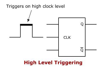
When a flip flop is required to respond at its HIGH state, a HIGH level triggering method is used. It is mainly identified from the straight lead from the clock input. Take a look at the symbolic representation shown below.

- High Level Triggering
2. Low Level Triggering
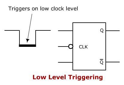
When a flip flop is required to respond at its LOW state, a LOW level triggering method is used.. It is mainly identified from the clock input lead along with a low state indicator bubble. Take a look at the symbolic representation shown below.

- Low Level Triggering
3. Positive Edge Triggering
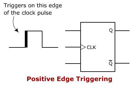
When a flip flop is required to respond at a LOW to HIGH transition state, POSITIVE edge triggering method is used. It is mainly identified from the clock input lead along with a triangle. Take a look at the symbolic representation shown below.

- Positive Edge Triggering
4. Negative Edge Triggering
When a flip flop is required to respond during the HIGH to LOW transition state, a NEGATIVE edge triggering method is used.. It is mainly identified from the clock input lead along with a low-state indicator and a triangle. Take a look at the symbolic representation shown below.

- Negative Edge Triggering
Clock Pulse Transition
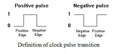
The movement of a trigger pulse is always from a 0 to 1 and then 1 to 0 of a signal. Thus it takes two transitions in a single signal. When it moves from 0 to 1 it is called a positive transition and when it moves from 1 to 0 it is called a negative transition. To understand more take a look at the images below.

- Clock Pulse Transition
The clocked flip-flops already introduced are triggered during the 0 to 1 transition of the pulse, and the state transition starts as soon as the pulse reaches the HIGH level. If the other inputs change while the clock is still 1, a new output state may occur. If the flip-flop is made to then the multiple-transition problem can be eliminated.
The multi-transition problem can be stopped is the flip flop is made to respond to the positive or negative edge transition only, other than responding to the entire pulse duration
Share this on your favourite network


0 comments:
Post a Comment