Search This Blog

Powered by Blogger.

Translate

Home » » Parking sensor circuit

Parking sensor circuit


Description.
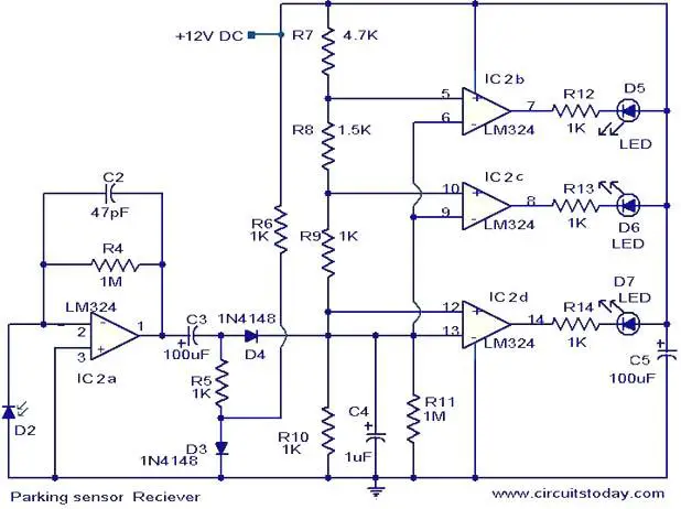
This simple circuit can be used as an aid for sensing the distance between the rear bumper of the car and any obstacle behind the car. The distance can be understood from the combination of the LEDs (D5 to D7) glowing. At 25cm D7 will glow, at 20 cm D7&D6 will glow and at 5cm D7, D6 and D5 will glow. When the obstacle is beyond 25 cm none of the above LEDs will glow.
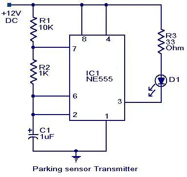
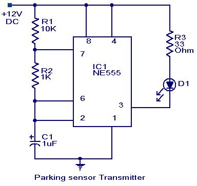
Two ICs are used in the circuit. The IC1 (NE555) is wired as an astable multivibrator for driving the IR Diode D1 to emit IR pulses. The operating frequency of the transmitter is set to be 120Hz.The IR pulses transmitted by D1 will be reflected by the obstacle and received by the D2 (IR photo diode).The received signal will be amplified by IC2a.The peak of the amplified signal will be detected by the diode D4 and capacitor C4.R5 and R6 compensates the forward voltage drop of D4.The output voltage of the peak detector will be proportional to the distance between car’s bumper and obstacle. The output of peak detector is given to the inputs of the other three comparators IC2b,IC2c and IC2d inside the IC2(LM324).The comparators switch the status LEDs according to the input voltage their inverting inputs and reference voltages at their non inverting inputs. Resistances R7 to R10 are used to set the reference voltages for the comparators.
Circuit diagram with Parts list.
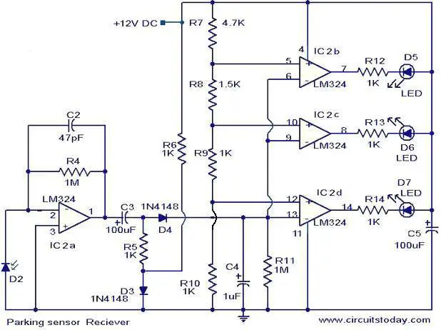
parking-_sensor-_receiver-_circuit.JPG

parking-sensor-_transmitter.JPG


Notes.
  • Assemble the circuit on a good quality PCB or common board.
  • The D1 & D2 must be mounted close (~2cm) to each other, looking in same direction.
  • The D1 can be a general purpose IR LED.
  • The D2 can be general purpose IR photo diode with sun filter.
  • The transmitter as well as receiver can be powered from the car battery.
  • For proper working of the circuit, some trial and error is needed with the position of D1 and D2 on the dash board.
  • All capacitors must be rated 25V.
  • The ICs must be mounted on holders

Share this on your favourite network

0 comments:

Post a Comment

Page Rank

google pagerank

Write For Us

Submit a Guest Post

Find us on Facebook

Categories

555 Timer IC 7 segment Display 8051 Project AC Circuits Adafruit Alarms Amplifier Circuits Analog Circuits android Arduino arm processor Assembly Languange Atmel Atom Size Audio Circuits augmented reality Automotive Circuits avr Battery Circuits Bicycle Gurad bluetooth Cable TV Circuits Cambridge University Camera Technology Circuit Boards Clipping And Clamping Circuits Clocking And Timer Circuits Computing contact lens Contact Us Form Contests Controller Circuit Conversion Circuits Counter Circuits Digital Electronics diy circuits Downloads EFY EFYTimes Electronic Books Electronic Components Electronic Locks And Keys Engineering Fan Circuits Filter Circuits Fire Alarm free Frequency Fun And Game Circuits future Google Hack n Mod Ham Radio Circuits heart rate monitoring High Voltage Circuits Home Circuits IC Guide ieee Industrial Circuits Infrared Instructables Inventions ipad lcd Led Circuits Light Related Lighting Circuits Medical Circuits Meter Clocks Microcontrollers Microprocessors Mini Projects modules Movie maker NatGeo Navigation Notice Optical Fiber PC Circuits PCB Boards Physics pnp transistor Power Supplies Printing Projects Programmer Project Ideas Projectors Protection circuits Proximity Detectors Radar Radio Circuits Radio Transmitters Raspberry Raspberry Pie Remote Circuits Retis Lab RFID Robot Cars Robotics Science Science Alert Security And Safety Sensor Circuits Servo Motors Smallest Smartwatches sms Software solar cell sound application Spectram Switch Technology News Telephone Related Television Related Test And Measurement Circuits Thermal Projects Tone generator circuits Touch Screen Tutorials Wearables Wi-Fi Wireless
Like us on Facebook
Follow us on Twitter
Recommend us on Google Plus
Subscribe me on RSS