
Electronic Combination Lock Circuit
Description
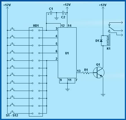
This is the circuit diagram of a simple electronic combination lock using IC LS 7220.This circuit can be used to activate a relay for controlling (on & off) any device when a preset combination of 4 digits are pressed.The circuit can be operated from 5V to 12V.
To set the combination connect the appropriate switches to pin 3,4,5 and 6 of the IC through the header.As an example if S1 is connected to pin 3, S2 to pin 4 , S3 to pin 5, S4 to pin 6 of the IC ,the combination will be 1234.This way we can create any 4 digit combinations.Then connect the rest of the switches to pin 2 of IC.This will cause the IC to reset if any invalid key is pressed , and entire key code has to be re entered.
When the correct key combination is pressed the out put ( relay) will be activated for a preset time determined by the capacitor C1.Here it is set to be 6S.Increase C1 to increase on time.
For the key pad, arrange switches in a 3X4 matrix on a PCB.Write the digits on the keys using a marker.Instead of using numbers I wrote some symbols!.The bad guys will be more confused by this.
Electronic Lock Circuit Diagram .

Pin Assignment of LS7220.

Parts List
C1 1 1uF 25V Electrolytic Capacitor
C2 1 220uF 25V Electrolytic Capacitor
R1 1 2.2K 1/4W Resistor
Q1 1 2N3904 NPN Transistor 2N2222
D1 1 1N4148 Rectifier Diode 1N4001-1N4007
K1 1 12V SPDT Relay Any appropriate relay with 12V coil
U1 1 LS7220 Digital Lock IC
S1-S12 12 SPST Momentary Pushbutton Keypad (see notes)
HD1 1 12 Position Header
Share this on your favourite network


0 comments:
Post a Comment