Diode Clippers – A study of various Clipping Circuits
This article explains the working of different diode clipper circuits like Positive and Negative Diode Clippers, Biased Clipper circuit, and Combinational Clipper Circuit with the help of circuit diagrams and waveforms.
The basic components required for a clipping circuit are – an ideal diode and a resistor. In order to fix the clipping level to the desired amount, a dc battery must also be included. When the diode is forward biased, it acts as a closed switch, and when it is reverse biased, it acts as an open switch. Different levels of clipping can be obtained by varying the amount of voltage of the battery and also interchanging the positions of the diode and resistor.
Depending on the features of the diode, the positive or negative region of the input signal is “clipped” off and accordingly the diode clippers may be positive or negative clippers.
There are two general categories of clippers: series and parallel (or shunt). The series configuration is defined as one where diode is in series with the load, while the shunt clipper has the diode in a branch parallel to the load.
1. Positive Clipper and Negative Clipper
Positive Diode Clipper
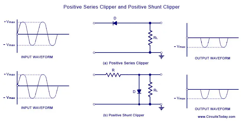
In a positive clipper, the positive half cycles of the input voltage will be removed. The circuit arrangements for a positive clipper are illustrated in the figure given below.
As shown in the figure, the diode is kept in series with the load. During the positive half cycle of the input waveform, the diode ‘D’ is reverse biased, which maintains the output voltage at 0 Volts. Thus causes the positive half cycle to be clipped off. During the negative half cycle of the input, the diode is forward biased and so the negative half cycle appears across the output.
In Figure (b), the diode is kept in parallel with the load. This is the diagram of a positive shunt clipper circuit. During the positive half cycle, the diode ‘D’ is forward biased and the diode acts as a closed switch. This causes the diode to conduct heavily. This causes the voltage drop across the diode or across the load resistance RL to be zero. Thus output voltage during the positive half cycles is zero, as shown in the output waveform. During the negative half cycles of the input signal voltage, the diode D is reverse biased and behaves as an open switch. Consequently the entire input voltage appears across the diode or across the load resistance RL if R is much smaller than RL
Actually the circuit behaves as a voltage divider with an output voltage of [RL / R+ RL] Vmax = -Vmax when RL >> R
Negative Diode Clipper
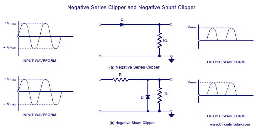
The negative clipping circuit is almost same as the positive clipping circuit, with only one difference. If the diode in figures (a) and (b) is reconnected with reversed polarity, the circuits will become for a negative series clipper and negative shunt clipper respectively. The negative series and negative shunt clippers are shown in figures (a) and (b) as given below.
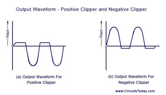
In all the above discussions, the diode is considered to be ideal one. In a practical diode, the breakdown voltage will exist (0.7 V for silicon and 0.3 V for Germanium). When this is taken into account, the output waveforms for positive and negative clippers will be of the shape shown in the figure below.
2. Biased Positive Clipper and Biased Negative Clipper
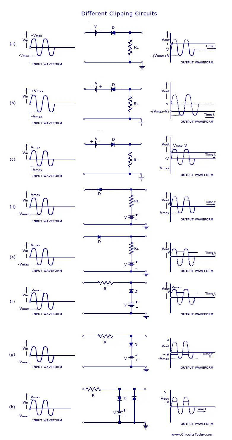
A biased clipper comes in handy when a small portion of positive or negative half cycles of the signal voltage is to be removed. When a small portion of the negative half cycle is to be removed, it is called a biased negative clipper. The circuit diagram and waveform is shown in the figure below.
TIn a biased clipper, when the input signal voltage is positive, the diode ‘D’ is reverse-biased. This causes it to act as an open-switch. Thus the entire positive half cycle appears across the load, as illustrated by output waveform [figure (a)]. When the input signal voltage is negative but does not exceed battery the voltage ‘V’, the diode ‘D’ remains reverse-biased and most of the input voltage appears across the output. When during the negative half cycle of input signal, the signal voltage becomes more than the battery voltage V, the diode D is forward biased and so conducts heavily. The output voltage is equal to ‘- V’ and stays at ‘- V’ as long as the magnitude of the input signal voltage is greater than the magnitude of the battery voltage, ‘V’. Thus a biased negative clipper removes input voltage when the input signal voltage becomes greater than the battery voltage. Clipping can be changed by reversing the battery and diode connections, as illustrated in figure (b).
Some of other biased clipper circuits are given below in the figure. While drawing the wave-shape of the output basic principle discussed above are followed. The diode has been considered as an ideal one.
3. Combination Clipper
When a portion of both positive and negative of each half cycle of the input voltage is to be clipped (or removed), combination clipper is employed. The circuit for such a clipper is given in the figure below.
The action of the circuit is summarized below. For positive input voltage signal when input voltage exceeds battery voltage ‘+ V1‘ diode D1 conducts heavily while diode ‘D2‘ is reversed biased and so voltage ‘+ V1‘ appears across the output. This output voltage ‘+ V1‘ stays as long as. the input signal voltage exceeds ‘+ V1‘. On the other hand for the negative input voltage signal, the diode ‘D1‘ remains reverse biased and diode ‘D2‘ conducts heavily only when input voltage exceeds battery voltage ‘V2‘ in magnitude. Thus during the negative half cycle the output stays at ‘- V2‘ so long as the input signal voltage is greater than ‘-V2‘.
Drawbacks of Series and Shunt Diode Clippers
- In series clippers, when the diode is in ‘OFF’ position, there will be no transmission of input signal to output. But in case of high frequency signals transmission occurs through diode capacitance which is undesirable. This is the drawback of using diode as a series element in such clippers.
- In shunt clippers, when diode is in the ‘off condition, transmission of input signal should take place to output. But in case of high frequency input signals, diode capacitance affects the circuit operation adversely and the signal gets attenuated (that is, it passes through diode capacitance to ground).
Share this on your favourite network


0 comments:
Post a Comment