Search This Blog

Powered by Blogger.

Translate

There's a 'Desert' in The Middle of The Pacific. Here's What Lives There

In the centre of the South Pacific, there's a place as far away from land as anyone on Earth could ever hope to get. The ocean is different there.

These distant waters lie at the heart of the South Pacific Gyre, the centre of which holds the 'oceanic pole of inaccessibility': the ocean's remotest extreme, aka Point Nemo (a name meaning 'no-one'), famous otherwise for being a spacecraft cemetery.

But aside from the ghosts of burnt-up satellites, what dwells under these far-off waves?

Not much, scientists have long thought. Despite taking up 10 percent of the ocean's surface, the South Pacific Gyre (SPG) – the largest of Earth's five giant ocean-spanning current systems – is generally considered a 'desert' in terms of marine biology.

Nonetheless, stuff does live there, even if organic life in these waters (and the seabed below it) is few and far between, due to a range of factors.

These include distance from land (and the nutrient matter it provides), the way water swirling currents isolate the centre of the gyre from the rest of the ocean, and high UV levels in this part of the ocean.

In truth, though, we don't actually know all that much about the life-forms that inhabit the SPG, largely because of how hard it is to study this oceanic desert – due to both its extreme remoteness, and also how large it is, covering about 37 million square kilometres (14 million square miles).

Despite the challenges, a recent international research effort has given us what the scientists claim is an unparalleled glimpse at the microbial creatures that exist in these waters.

During a six-week expedition aboard the German research vessel FS Sonne from December 2015 to January 2016, a crew led by the Max Planck Institute for Marine Microbiology sailed a 7,000-kilometre (4,350 miles) journey through the SPG from Chile to New Zealand.

En route, they sampled the microbial populations of the remote waters at depths between 20 to 5,000 metres (65 ft to 16,400 ft), using a newly developed analysis system that enabled the researchers to sequence and identify organic samples en route in as little as 35 hours.

016 south pacific gyre 1 
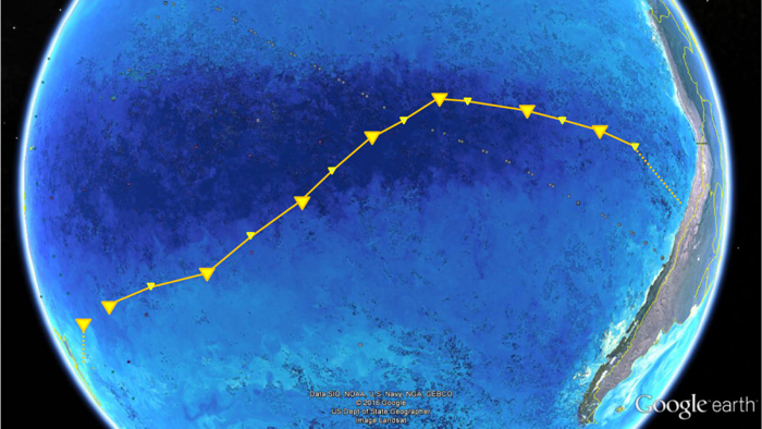
(Max Planck Institute for Marine Microbiology/Google Earth/NASA)

Above: FS Sonne's path crossing the SPG from Chile to New Zealand.

"To our surprise, we found about a third less cells in South Pacific surface waters compared to ocean gyres in the Atlantic", said one of the researchers, microbial ecologist Bernhard Fuchs, back in July 2019.

"It was probably the lowest cell numbers ever measured in oceanic surface waters."

Among the microbes the team found, 20 major bacterial clades dominated the lot. These were mostly organisms scientists have encountered in other gyre systems, such as SAR11, SAR116, SAR86, Prochlorococcus, and more.

The distribution of these microbe communities depended largely on water depth, based around factors such as changes in temperature, nutrient concentrations, and availability of light.

One of the populations identified, called AEGEAN–169, was particularly numerous in the surface waters of the SPG, whereas previous research had only discovered them at 500-metre depths.

"This indicates an interesting potential adaptation to ultraoligotrophic [low in biological productivity] waters and high solar irradiance", said one of the team, microbiologist Greta Reintjes.

"It is definitely something we will investigate further."

On the whole though, the sampling generally confirmed that the SPG is a "unique, ultraoligotrophic habitat", where low nutrient availability restricts growth to specialist oligotrophic organisms and creatures that have adapted to "extreme physicochemical conditions".

In other words, the SPG can't shake off its 'desert' reputation just yet, but there is a bright side to all that organic absence: these distant, almost lifeless waters are said to be the clearest ocean in all the world.

The findings were reported in Environmental Microbiology.

A version of this article was first published in July 2019.


Source: https://www.sciencealert.com

[TC] Physicists just built the world's smallest optical switch - based on a single atom


As our need for more data and faster transmissions grows, existing network infrastructure is being put under more strain than ever before. As a result, scientists are working hard to miniaturise these systems and switch from current electron-based computers to super-fast optics-based communications, where data is quite literally sent at the speed of light.
Now scientists working at ETH Zurich in Switzerland have made crucial progress in the design of a modulator - the device that converts electronic signals into optical ones. These devices are currently around 3 cm wide, which means when you have a data centre full of them, they take up a substantial amount of room. But this new modulator is based on an optical switch that uses just one atom.
As Gizmag's Colin Jeffrey reports, that's a level of miniaturisation that's surprised even the scientists themselves - it essentially allows light to pass through a gap that's smaller than the wavelength of light itself. A modulator built around this switch could be some 100,000 times smaller than the devices in use today.
Here's how it works: silver and platinum pads are placed on top of an optical waveguide made of silicon with just an atom's gap between them. Once voltage is applied to the silver pad, a single atom is drawn towards its furthermost point, closing up the gap and creating a circuit between the two pads. When voltage is removed, the atom retracts, and thus the modulator can transmit millions of switch signals every second.
But what about the physics-bending light compression? As the light is beamed across the waveguide, it gets converted into surface plasmon, made up of electrons that oscillate at the frequency of the laser light. These electrons can pass through the single atom gap before being reconverted on the other side. By reconfiguring the design of the modulator, the light is effectively squashed to squeeze through the gap.
"Until recently, even I thought it was impossible for us to undercut this limit,"said lead researcher, Jürg Leuthold. "This allows us to create a digital switch, as with a transistor. We have been looking for a solution like this for a long time."
Now the team wants to improve the modulator production process so it's suitable for large-scale use and reliable in operation - at the moment, only one out of every six attempts at fabrication is successful. Eventually, though, this single atom modulator could be helping to shift data around the planet faster than ever before.
Source: Science Alert

[TC] Frequency counter using arduino

Many guys here were asking for a frequency counter and at last I got enough time to make one.  This frequency counter using arduino is based on the UNO version and can count up to 40KHz. A 16×2 LCD display is used for displaying the frequency count. The circuit has minimum external components and directly counts the frequency. Any way the amplitude of the input frequency must not be greater than 5V. If you want to measure signals over than 5V, additional limiting circuits have to be added and i will show it some other time. Now just do it with 5V signals.
The frequency to be counted is connected to digital pin 12 of the arduino. pulseIn() function is used here for counting the frequency connected to pin 12. pulseIn() function counts the number of pulses (HIGH or LOW) coming to a particular pin of the arduino. The general syntax of this function is pulseIn(pin, value, time) where pin is the name of the pin, value is either HIGH or LOW and time is time for which the function to wait for a pulse. The function returns zero if there is no valid pulse with in the specified time. The pulseIn() function can count pulses with time period ranging from 10 μS to 3 minutes. Circuit diagram of the frequency counter using arduino is given below.


Potentimeter R1 is used to adjust the contrast of the LCD screen. Resistor R2 limits the current through the back light LED.
In the program, high time and low time of the input signal is measured using separate pulseIn() functions. Then the high and low times are added together to get the total time period of the signal. Frequency is just 1/time period in seconds. The pulseIn() function returns the time period in microseconds. Total timeperiod in microseconds first divided by 1000. Then 1000 is divided by the result to get the frequency in hertz. The program of the frequency counter using arduino is shown below.

Program.

#include <LiquidCrystal.h>
int input=12;

int high_time;
int low_time;
float time_period;
float frequency;
LiquidCrystal lcd(7, 6, 5, 4, 3, 2);
void setup()
{
pinMode(input,INPUT);
lcd.begin(16, 2);
}
void loop()
{
lcd.clear();
lcd.setCursor(0,0);
lcd.print("Frequency Meter");

high_time=pulseIn(input,HIGH);
low_time=pulseIn(input,LOW);

 
time_period=high_time+low_time;
time_period=time_period/1000;
frequency=1000/time_period;
lcd.setCursor(0,1);
lcd.print(frequency);
lcd.print(" Hz");
delay(500);
}
The circuit can be powered through the 9V external power jack of the arduino. 5V DC required at some parts of the circuit can be tapped from the built in 5V regulator of the arduino itself. This is actually a simple counter circuit using arduino. We can modify this circuit for other applications like tachometer, intrusion counter etc.

Source:


http://www.circuitstoday.com/

[TC] Heart rate monitor using 8051

This article is about a simple heart rate monitor using 8051 microcontroller. Like the previous 8051 projects, AT89S51 is the microcontroller used here. The device senses the heart rate from the finger tip using IR reflection method and displays it on a three digit seven segment display in beats per minute. The circuit has an accuracy of 4 beats per minute and it is very easy to use. In medical terms, the technique used here for sensing heart rate is called photoplethysmography.

Photoplethysmography.

Photoplethysmography is the process of optically estimating the volumetric measurement of an organ. Pulse oximetry, cardiovascular monitoring, respiration detection, heart rate monitoring etc are few common applications of photoplethysmography. Let us have a look at the application of photoplethysmography in heart rate monitoring from the figer tip. When the heart expands (diastole) the volume of blood inside the finger tip increases and when the heart contrcats (systole) the volume of blood inside the finger tip decreases. The resultant pulsing of blood volume inside the finger tip is directly proportional to the heart rate and if you could some how count the number of pulses in one minute, that’s the heart rate in beats per minute (bpm). For this an IR transmitter /receiver pair is placed in close contact to the finger tip. When the heart beats, the volume of blood cells under the sensor increases and this reflects more IR waves to sensor and when there is no beat the intensity of the reflected beam decreases. The pulsating reflection is converted to a suitable current or voltage pulse by the sensor. The sensor output is processed by suitable electronic circuits to obtain a visible indication (digital display or graph).

Heart rate monitor using 8051.

Circuit diagram.


Working of the heart rate monitor

LTH1550-01 photo interruptor forms the photoplethysmographic sensor here. LTH1550-01 is simply a IR diode – photo transistor pair in single package. The front side of the IR diode and photo transistor are exposed and the remaining parts are well isolated. When the finger tip is placed over the sensor the volumetric pulsing of  the blood volume inside the finger tip due to heart beat varies the intensity of the reflected beam and this variation in intensity is according to the heart beat.
When more light falls on the photo transistor it conducts more, its collector current increases and so its collector voltage decreases. When less light falls on the phototransistor it conducts less, its collector current decreases and so its collector voltage decreases. This variation in the collector voltage will be proportional to the heart rate. Any way this voltage variation is so feeble and additional signal conditioning stages are necessary to convert it into a microcontroller  recognizable form.
The next part of the circuit consists of a two active low pass filters using opampLM324.  The LM324 is a quad opamp that can be operated from a single rail supply. Resistor R23, R17 and capacitor C5 sets the gain and cut off frequency of the first filter. With the given component values, gain will be 101 and cut off frequency will be 2.5Hz. The gain and cut off frequency are determined using the following equations.
Voltage gain Av =1 + (R17 / R23)
Cut off frequency Fc= 1/(2Ï€ *R17*C5)
The second low pass filter also have the same parameters. The two low pass filters form a very critical part of the circuit as any noise or false signals passing to the microcontroller stage will produce disastrous results. The output of the filter stage will be a voltage level fluctuating between 0 and 0.35 volts and this fluctuation is converted into a 0 to 5V swing using the comparator  based on the third opamp (IC1c). The reference voltage of the comparator is set to 0.3V. When ever the output voltage of the filter stage goes above 0.3V, the output of the comparator goes to zero and whenever the output voltage of the filter stage goes below 0.3V, the output of the comparator goes to positive saturation. The result will be a neat pulse fluctuating between 0 and 5V at a rate equal to the heart rate. This pulse is fed to the microcontroller for counting.

Program.

ORG 000H // originMOV DPTR,#LUT // moves starting address of LUT to DPTRMOV P1,#00000000B // sets P1 as output portMOV P0,#00000000B // sets P0 as output portMAIN: MOV R6,#230D // loads register R6 with 230D SETB P3.5 // sets P3.5 as input port MOV TMOD,#01100001B // Sets Timer1 as Mode2 counter & Timer0 as Mode1 timer MOV TL1,#00000000B // loads TL1 with initial value MOV TH1,#00000000B // loads TH1 with initial value SETB TR1 // starts timer(counter) 1BACK: MOV TH0,#00000000B // loads initial value to TH0 MOV TL0,#00000000B // loads initial value to TL0 SETB TR0 // starts timer 0HERE: JNB TF0,HERE // checks for Timer 0 roll over CLR TR0 // stops Timer0 CLR TF0 // clears Timer Flag 0 DJNZ R6,BACK CLR TR1 // stops Timer(counter)1 CLR TF0 // clears Timer Flag 0 CLR TF1 // clears Timer Flag 1 ACALL DLOOP // Calls subroutine DLOOP for displaying the count SJMP MAIN // jumps back to the main loopDLOOP: MOV R5,#252DBACK1: MOV A,TL1 // loads the current count to the accumulator MOV B,#4D // loads register B with 4D MUL AB // Multiplies the TL1 count with 4 MOV B,#100D // loads register B with 100D DIV AB // isolates first digit of the count SETB P1.0 // display driver transistor Q1 ON ACALL DISPLAY // converts 1st digit to 7seg pattern MOV P0,A // puts the pattern to port 0 ACALL DELAY ACALL DELAY MOV A,B MOV B,#10D DIV AB // isolates the second digit of the count CLR P1.0 // display driver transistor Q1 OFF SETB P1.1 // display driver transistor Q2 ON ACALL DISPLAY // converts the 2nd digit to 7seg pattern MOV P0,A ACALL DELAY ACALL DELAY MOV A,B // moves the last digit of the count to accumulator CLR P1.1 // display driver transistor Q2 OFF SETB P1.2 // display driver transistor Q3 ON ACALL DISPLAY // converts 3rd digit to 7seg pattern MOV P0,A // puts the pattern to port 0 ACALL DELAY // calls 1ms delay ACALL DELAY CLR P1.2 DJNZ R5,BACK1 // repeats the subroutine DLOOP 100 times MOV P0,#11111111B RET DELAY: MOV R7,#250D // 1ms delay DEL1: DJNZ R7,DEL1 RET DISPLAY: MOVC A,@A+DPTR // gets 7seg digit drive pattern for current value in A CPL A RETLUT: DB 3FH // LUT starts here DB 06H DB 5BH DB 4FH DB 66H DB 6DH DB 7DH DB 07H DB 7FH DB 6FHEND

About the program.

For the counting purpose both the timers of 8051 (Timer0 and Timer1) are used. Timer 1 is configured as an 8 bit auto reload counter for registering the number of incoming zero going pulses and Timer0 is configured as a 16 bit timer which generate the necessary 1 second time span for the Timer1 to count.For counting the number of beats Timer0 and Timer1 are used. Timer1 is set as an 8 bit auto reload counter for counting the the number of pulses (indicating the heart beat) and Timer0 is set as a 16 bit timer which generates a 65536uS delay. When looped 230 times it will produce a 15 second time span (230 x 65536uS =15S)  for the Timer 1 to count. The number of counts obtained in 15 seconds is multiplied by 4 to obtain the heart rate in beats per minute.
 The Timer 0 which generates the 1 second time span is configured in Mode 1 (16 bit timer). So the maximum it can count is 2^16 and it is 65536. In 8051 the crystal frequency is divided by 12 using an internal frequency divider network before applying it as a clock for the timer. That means the timer will increment by one for every 1/12th of the crystal frequency. For an 8051 based system clocked by a 12MHz crystal, the time taken for one timer increment will be 1µS (ie; 1/12MHz). So the maximum time delay that can be obtained using one session of the timer will be 65536µS. Go through this article Delay using 8051 timer for a better grasp.
Setting up the circuit.
When power is switched ON, the indicator LED D4 will glow an continues in that state. Now place your finger tip over the sensor and adjust preset R14 so that the LED D4 starts blinking. After you got the LED blinking, reset the power and wait for 15 seconds. The display will show your heart rate in beats per minute.
Source: http://www.circuitstoday.com/heart-rate-monitor-using-8051

5 Microcontroller Based Projects You Must Not Miss!

Looking for a microcontroller based project? From our collection of microcontroller based projects, we bring to you 5 super cool projects. Have fun!


A tachometer is nothing but a simple electronic digital transducer. Normally, it is used for measuring the speed of a rotating shaft. The number of revolutions per minute (rpm) is valuable information for understanding any rotational system. For example, there is an optimum speed for drilling a particular-size hole in a particular metal piece; there is an ideal sanding disk speed that depends on the material being finished. You may also want to measure the speed of fans you use.

Here is an easy-to-construct temperature indicator-cum-controller that can be interfaced with a heater coil to maintain the ambient room temperature. The controller is based on Atmega8535 microcontroller, which makes it dynamic and faster, and uses an LCD module to display and two keys to increase or decrease the set values.

Digital wall clocks, table clocks and desk clocks with pointer or LCD display are readily available in the market. Here we present a clock that can be built in a small budget using AT89C2051 microcontroller. Additional feature of the clock is that the time display is visible even in the dark.

Microcontroller-based embedded systems play major role in industrial automation. One such widely used system is the programmable timer.

The circuit that uses microcontroller AT89C51 can control four devices from a distance of upto 30 metres wirelessly. An LCD module is used to show the device number and preset control time at the transmitter module.

Source: http://electronicsforu.com/

Registered "www.todays-circuits.com" For Our Blog


Finally after long patience we purchased Web Domain 
"www.todays-circuits.com
and The Same WIll Be Activated in next 2 days and "todayscircuits.blogspot.com
will be redirected. 

Stay Tuned. 

Thanking You For Your Huge Support.

      Yours Sincerely,
"Admin"

$20 Robot From MIT Wins AFRON Design Challenge Made From Arduino Board


Robots, as anyone who has ever attempted to build or buy or fix a robot knows, tend to be expensive. This presents a problem for people who want to start learning about robotics, because getting a foot in the door with an actual robot to work on generally involves a substantial up-front investment in hardware. And for places where teachers and students don't have huge piles of money to throw at technology, this can mean that robots just don't happen.
The African Robotics Network (AFRON) and IEEE Robotics and Automation Society (RAS) collectively sponsor a biennial design challenge to "collaboratively create an educational robot that is an order of magnitude less expensive than existing products, to inspire young people around the world." For 2013/2014, MIT took home a win with their MIT SEG robot, a 3D-printed, Arduino-based wheeled robot that can be built for $20 in five steps with no training or tools.
The completed MIT SEG is shown in the picture above; below is an image of the unassembled robot in its entirety:
All you have to do to go from this to robot is fold up the chassis (the squareish bits at the lower left), fold the wheels together, fit the electronics in, stick the wheels onto the servos, and that's it, you're done. Here's the bill of materials:
MIT points out that if you don't go with a breakout board for the Arduino and instead wire-wrap the headers directly, you can drop the cost by about $2.50 per bot. You also need a programmer and a charger, which together will run you another $18.20, but these can be shared among multiple robots.
So great, you've got a robot that's easy to make and is dirt cheap. What can it do? Out of the box, MIT SEG includes an Arduino compatible drag-and-drop graphical programming interface. The LED and photosensor can be used to determine whether the robot is looking at something black, white, or gray, meaning that you can do line-following and some obstacle avoidance right away, and MIT has put together a bunch of examples and an entire curriculum that classrooms can follow. Plus, since the robot has an Arduino for a brain, you can leverage all of the hardware (and the community) that's been plugging into Arduinos for the last few years.
Second place in the hardware portion of the Design Challenge went toHarvard's $10.70 AERobot:
The Ultra Affordable Educational Robot Project Design Challenge also includes categories for Software, Curriculum, and Community Challenges.
"The AFRON organizers and RAS sponsors admire the ingenuity of the submissions in all categories," said Ken Goldberg, a roboticist at UC Berkeley who co-founded AFRON with Ayorkor Korsah, a professor of computer science at Ashesi University, in Ghana. Goldberg noted that two winning projects from Africa, PanyaBot (Kenya) and ARX LollyBot (Ghana), continue to make major advances in the Software and Community Challenge categories. "We look forward to connecting all the participants to share ideas and designs for next steps via the AFRON network, which anyone worldwide can join at no cost," he said.

Source : http://spectrum.ieee.org/automaton/robotics/diy/20-robot-mit-wins-afron-design-challenge

Page Rank

google pagerank

Write For Us

Submit a Guest Post

Find us on Facebook

Categories

555 Timer IC 7 segment Display 8051 Project AC Circuits Adafruit Alarms Amplifier Circuits Analog Circuits android Arduino arm processor Assembly Languange Atmel Atom Size Audio Circuits augmented reality Automotive Circuits avr Battery Circuits Bicycle Gurad bluetooth Cable TV Circuits Cambridge University Camera Technology Circuit Boards Clipping And Clamping Circuits Clocking And Timer Circuits Computing contact lens Contact Us Form Contests Controller Circuit Conversion Circuits Counter Circuits Digital Electronics diy circuits Downloads EFY EFYTimes Electronic Books Electronic Components Electronic Locks And Keys Engineering Fan Circuits Filter Circuits Fire Alarm free Frequency Fun And Game Circuits future Google Hack n Mod Ham Radio Circuits heart rate monitoring High Voltage Circuits Home Circuits IC Guide ieee Industrial Circuits Infrared Instructables Inventions ipad lcd Led Circuits Light Related Lighting Circuits Medical Circuits Meter Clocks Microcontrollers Microprocessors Mini Projects modules Movie maker NatGeo Navigation Notice Optical Fiber PC Circuits PCB Boards Physics pnp transistor Power Supplies Printing Projects Programmer Project Ideas Projectors Protection circuits Proximity Detectors Radar Radio Circuits Radio Transmitters Raspberry Raspberry Pie Remote Circuits Retis Lab RFID Robot Cars Robotics Science Science Alert Security And Safety Sensor Circuits Servo Motors Smallest Smartwatches sms Software solar cell sound application Spectram Switch Technology News Telephone Related Television Related Test And Measurement Circuits Thermal Projects Tone generator circuits Touch Screen Tutorials Wearables Wi-Fi Wireless
Like us on Facebook
Follow us on Twitter
Recommend us on Google Plus
Subscribe me on RSS